This Project was developed some time ago for a client that gladly let me write something about it here, although not in detail. In the next lines, I will go along some of the thought processes I used to project and build everything. The client in question works by renting VR goggles to parties and corporative events. During a gaming session, the clients would have the visual stimulation of the VR goggles and the vibration of the controller in their hands, but my client wanted more immersion in the form of a special seat that would vibrate at the same time as the controller. In order to achieve that, he had a specially built “cockpit-like” structure and now he only needed the electronics to control a “mysterious” vibration actuator. This vibration actuator was an old back massager big and strong enough to shake the entire structure a lot. So at the principle, there were two challenges: how to make something vibrate at the same time as the controller and how to control the improvised actuator.
Hacking the controller
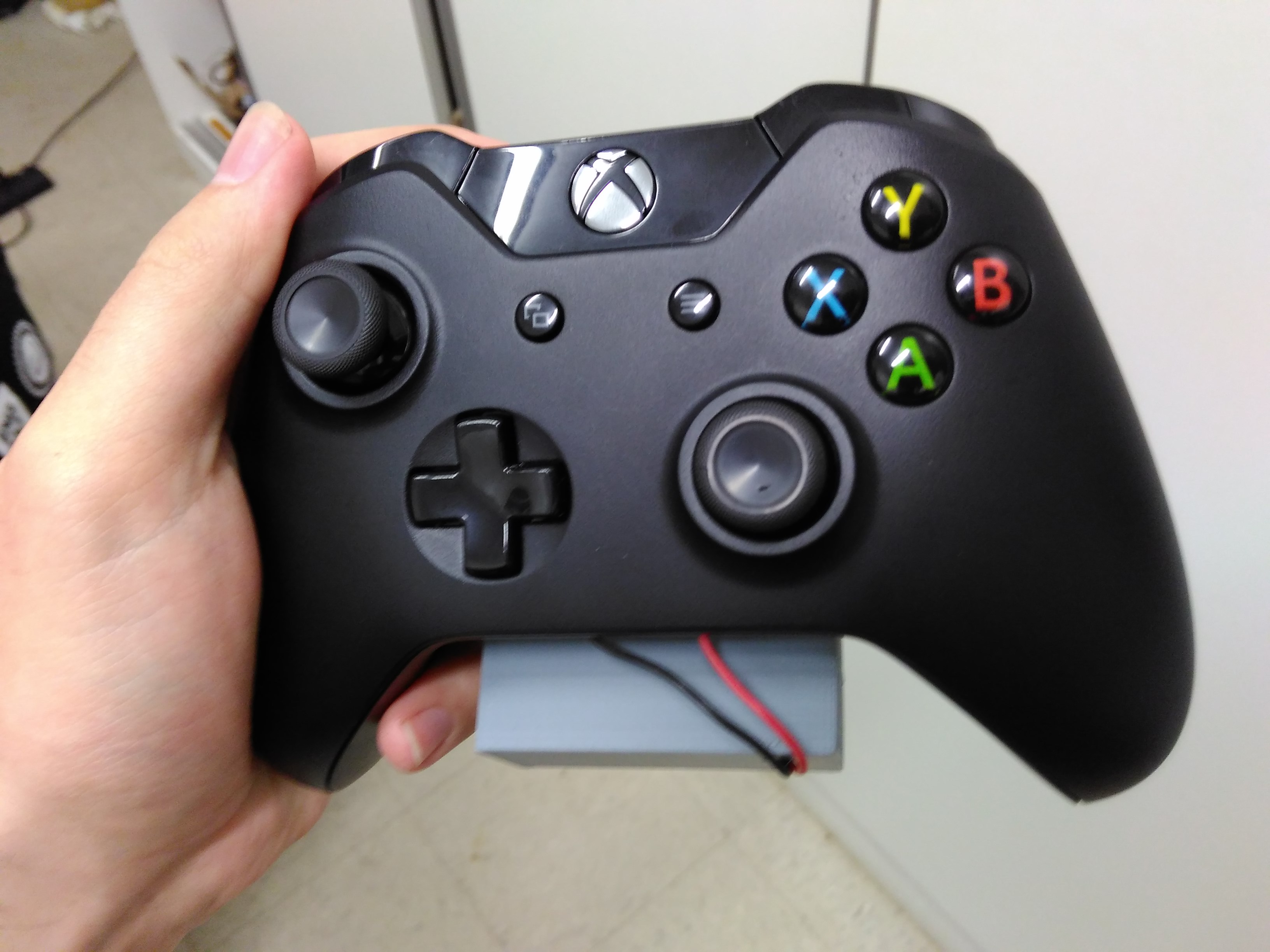
The controller was an XBOX ONE controller that vibrated through the asynchronous movement of two rumble motors inside of it. First of all, I need to know what kind of signal was being used to control this rumble motor. Happily, after a check with the oscilloscope, it was clear that those small electric motors were controlled by the good old PWM. Now I could simply use the “pulseIn()” Arduino function to extract this data in real-time. To send it to the cockpit I used a simple NRF24 module. The whole system was integrated into a PCB, powered by a 9V battery and placed in a special 3D printed enclosure. I designed this enclosure to fit at the back of the controller, the same way the battery cover would. At last, the controller part was done.
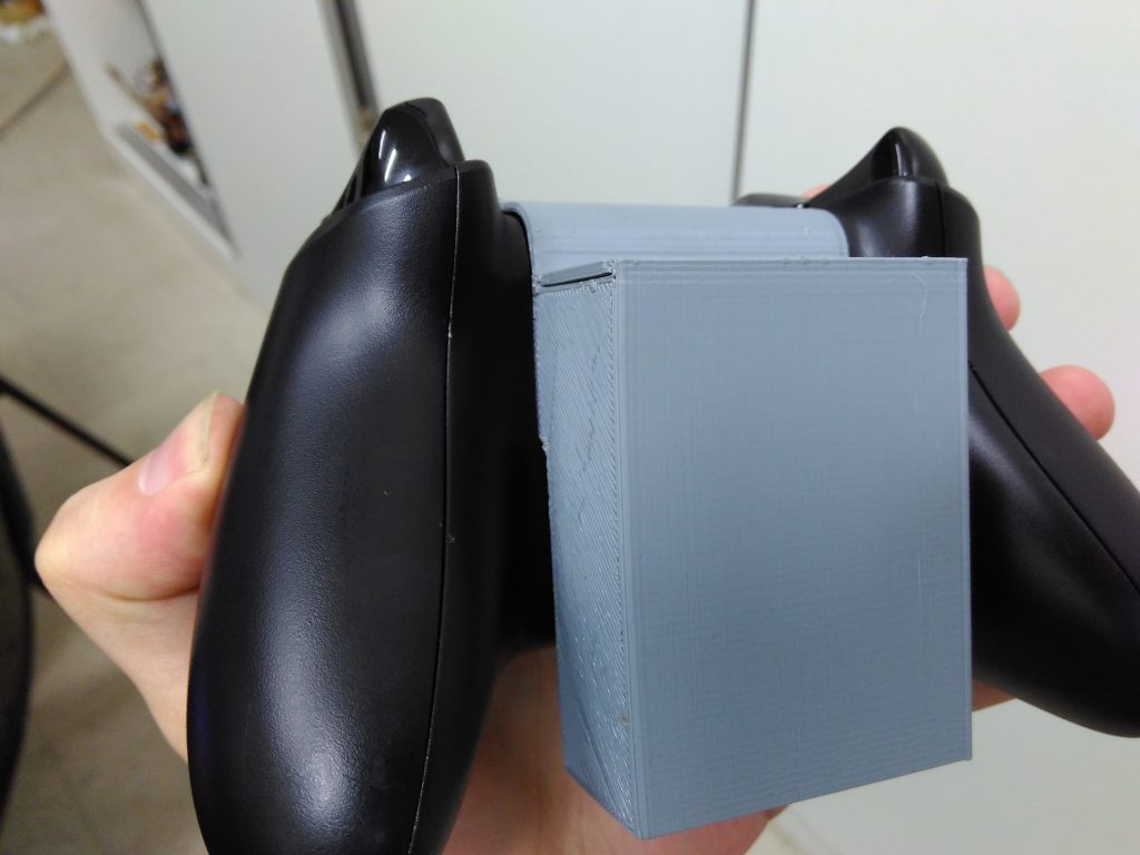
3D printed enclosure
Investigating the actuator
As previously stated, the actuator was an old back massager. It was a big plastic box connected to a knob through an RJ9 cable. The knob had a potentiometer look and feel to it, but I could not open it to be sure because it was sealed. So, to avoid breaking the Knob enclosure, I probed its ends with a multimeter and it worked pretty much as a potentiometer would. Based on these assumptions I made the educated guess to infer that the actuator was controlled by a simple potentiometer. Now I just needed to mimic the potentiometer digitally to control everything. A digital potentiometer was an obvious choice. Things got a little complicated when I was measuring the voltage and current for dimensioning the digital potentiometer. Apparently, the knob in question controlled 110V AC (obviously, mains power). With no available digital potentiometer (they are typically used to drive low-voltage electronic circuits) and no knowledge of the inner electronics of the actuator to design some kind of switching AC-AC converter, I needed to think on something out of the box. So I designed my own digital potentiometer for high AC voltage.
High AC voltage Digital potentiometer design
There is no secret to how a digital potentiometer works. It is basically a long line of resistors in
Integrating the system
Now that both challenges were solved, it was a question of connecting the pieces together. The controller data was being collected by an Arduino nano and broadcasted by an NRF24 module. Another NRF24 module was receiving this information and sending it to another Arduino, the one controlling the digital potentiometer. The digital potentiometer was connected to the actuator by an RJ9 cable. With all the systems in place, it was time for testing.
Results
After correcting some programming bugs and short circuits in the PCB the whole thing worked like a charm and the client got pretty satisfied. Below there is a video of the system being tested by some colleagues of mine.

